Matrix Systems
The NXA-B168M Matrix System delivers precise, repeatable RF routing and attenuation control for complex test setups. It features an intuitive GUI, supports Windows and Linux, and enables flexible path configuration, fading profiles, and control via USB and Ethernet in a compact, scalable design.
Frequency
200 – 8000
MHz
Matrix Size
16×8
matrix
Attenuation
0 – 95
dB
Step Size
0.25
dB
Isolation
90
dB
Connector
SMA
Female
Key Features
Engineered for continuous use
Extended Frequency Range
Operates across a broad spectrum from 200 MHz to 8 GHz, ensuring versatility for a wide array of testing applications.
24/7 Operation
Engineered for continuous use, supporting fully automated testing workflows to maximize efficiency and reliability in mission-critical environments.
Shielded and Precise
Complete shielding ensures highly accurate and interference-free measurements, ideal for precision testing in demanding RF environments.
Customizable Topologies
Tailored to customer specifications, supporting multiple network topologies for enhanced flexibility and optimized test setups.
High Dynamic Range
Offers up to 95 dB of attenuation with fine-grain control, adjustable in 0.25 dB increments, delivering exceptional precision for signal fading and attenuation simulations.
Tailored User Interface
Custom-designed software interfaces align with specific customer needs, providing an intuitive and efficient control experience for streamlined operations.
Target Applications
Built for real-world RF validation
The NXA-B168M is engineered for environments where accuracy, repeatability, and scale matter most to your testing methodology.
Wi-Fi communication systems
Cellular systems (5G/4G/3G/2G)
MIMO, Multipoint Radio Fading
Automated Test Equipment (ATE)
Specifications
Technical Data
Complete performance data for the NXA-B168M matrix attenuator.
Electrical Characteristics
| Parameter | Min | Typ | Max | Unit |
|---|---|---|---|---|
| Frequency Range (MHz) | 200 | — | 8000 | MHz |
| Impedance | — | 50 | — | Ω |
| Channel Inputs/Outputs | — | 16x8 | — | — |
| Attenuation Range | — | 95 | — | dB |
| Shielding | — | 90 | — | dB |
| Isolation between Channels | — | 90 | — | dB |
| Step Size | — | 0.25 | — | dB |
| Insertion Loss (< 2 GHz) | — | 21 | — | dB |
| Insertion Loss (< 4 GHz) | — | 26 | — | dB |
| Insertion Loss (< 7.5 GHz) | — | 30 | — | dB |
| Attenuation Accuracy | 0.25 | 1.5 | — | dB |
| Switching Speed | — | 2 | — | µs |
| Maximum Input Level (operating) | — | +28 | — | dBm |
| Maximum Input Level (absolute max) | — | +33 | — | dBm |
| Input IP3 | — | 58 | — | dBm |
| Operating modes | — | Uni/Bi-Directional | — | — |
| Control | — | GUI control or APIs | — | — |
| Power | — | Power over Ethernet (PoE) | — | — |
| Control Interface | — | Ethernet or USB | — | — |
Mechanical & Environmental
| Parameter | Details |
|---|---|
| Power Requirements | +5VDC (from USB port) – 1.1 Amps |
| Environmental | Operating Temperature: 0°C to +40°C |
| Physical Connections | Power Connector: USB Control: USB/Ethernet RF Connectors: SMA – female |
| Mechanical | Size (3RU): 17.0 × 18 × 5.23 inches Weight: 32 lbs / 14.5 kg |
Download Resources
Full datasheet with performance graphs, insertion loss curves, and mechanical drawings.
Download DatasheetNeed a custom config?
We design custom matrix sizes, topologies, and control interfaces to fit your lab.
Contact engineeringArchitecture
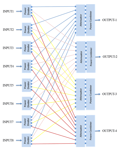
Functional Diagram
The 16×8 switching matrix routes any of the 16 inputs to any of the 8 outputs through independently controlled attenuation paths.